Variant combination air release and vacuum break valves safeguard pipelines from harmful vacuum conditions, whilst preserving system efficiency. The integral antishock mechanism provides additional protection against damaging surges caused by uncontrolled filling or pump stopages.
Before filling, pipelines are filled with air. As the pipeline fills, air travels along the pipeline toward the high points. Air valves placed at these locations discharge this air through large orifices to the atmosphere.
During normal operational conditions, unwanted air enters the air valves located at the high points along the pipeline. Once sufficient air accumulates in the valves, they will automatically release this air into the atmosphere, thereby maintaining pipeline efficiency.
The primary role of air valves is to admit air into pipelines to prevent damaging negative pressures that can arise under conditions such as:
• Isolation
• Interruption of supply
• Scouring
• Negative pressures during surge events.
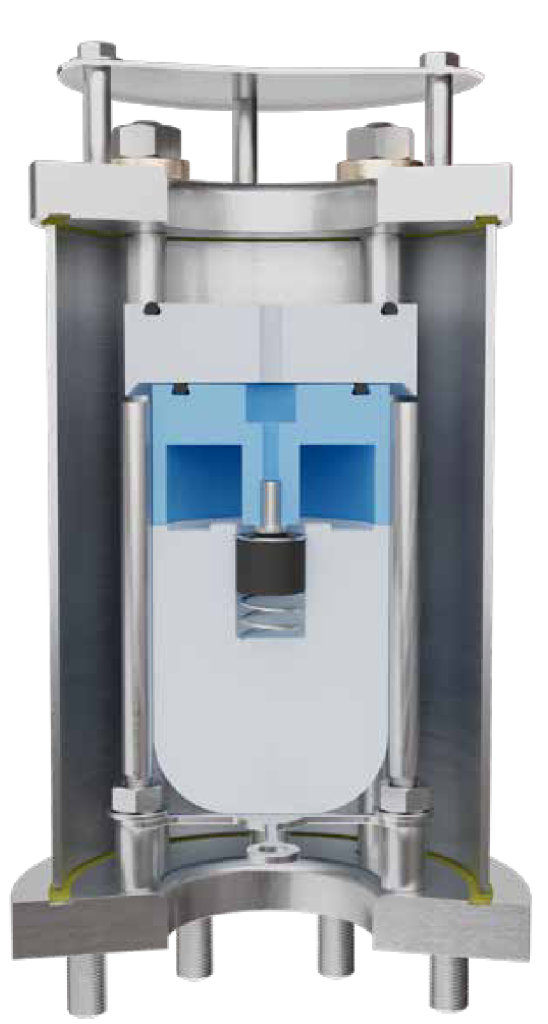
Variant air valves provide a full-bore, unobstructed flow path that maximizes air in-take capacity.
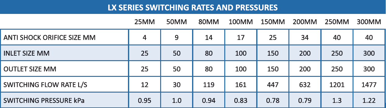
When airflow through the valve surpasses a predetermined threshold, the antishock float is activated and rises to partially restrict air discharge. This controlled restriction creates an air cushion within the pipeline, mitigating potentially damaging surges during events such as pump trips or rapid filling.
• Potable water
• Settled Raw Water
• High-capacity air discharge
• High-capacity air intake
• Pressurized air release
• Surge alleviation
• Optimal flow performance
• Lowest anti-shock switching rates
• Reliable sealing at low pressures (20 kPa)
• Compact, efficient design
• No dissimilar metal corrosion
• Stainless steel cover screen
• ¼ inch bleed port with plug
• Air-out only configuration
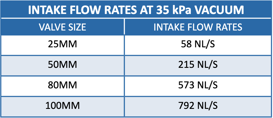
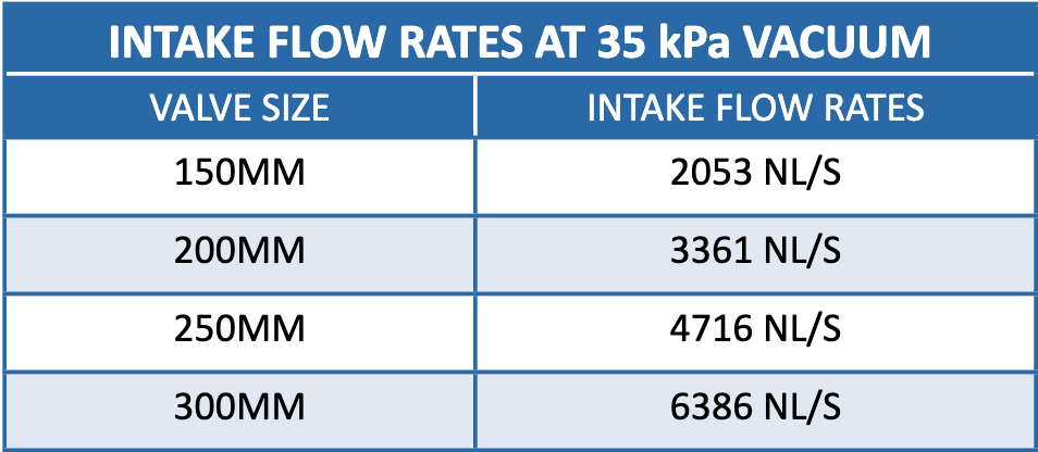
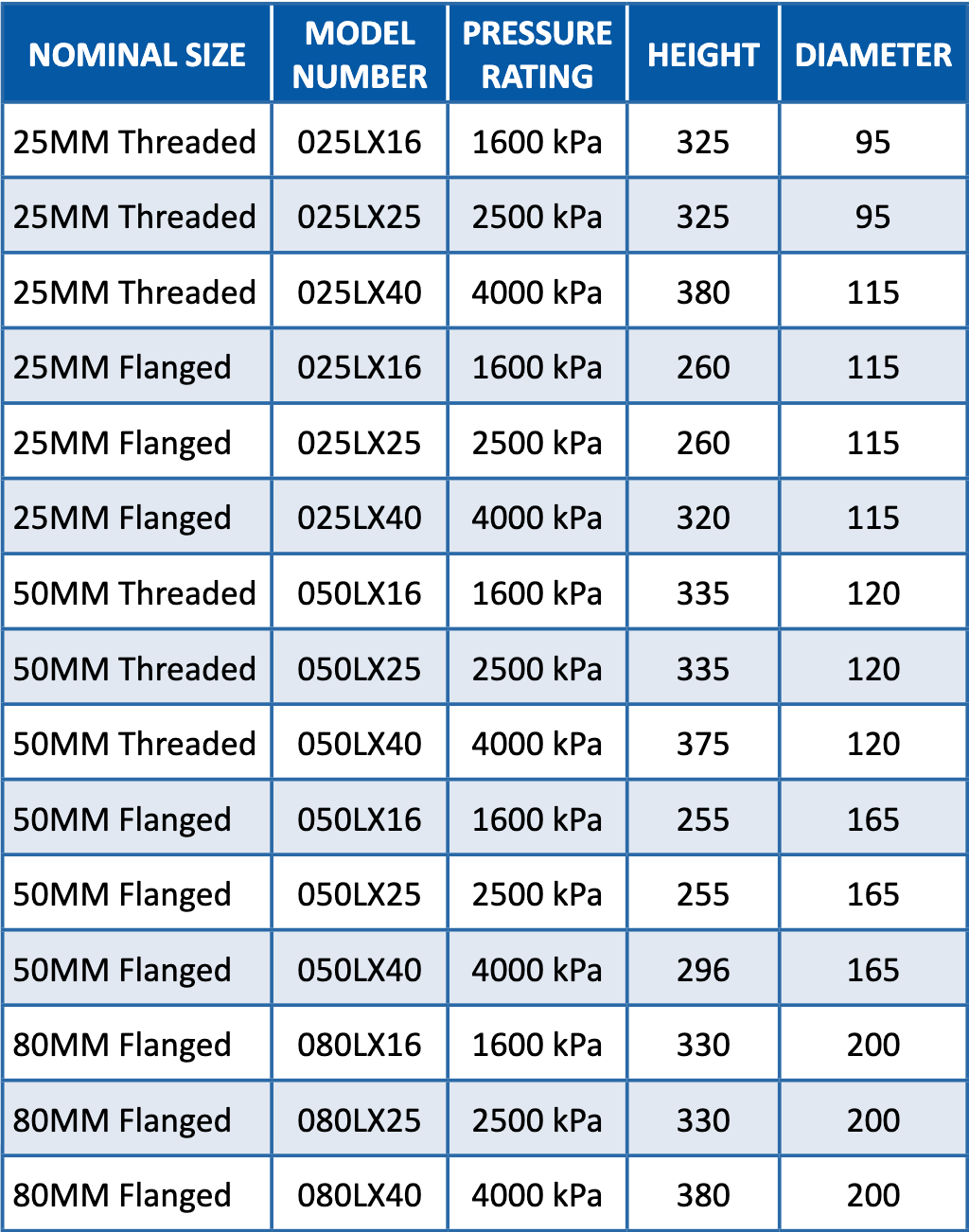
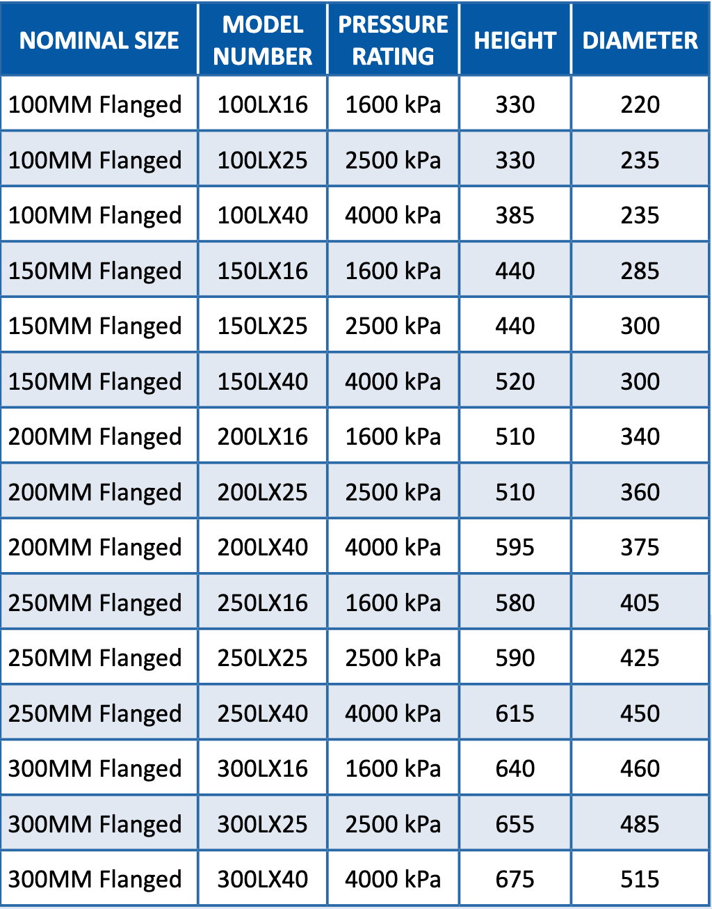
Correct sizing of air valves primarily depends on intake requirements under vacuum conditions. To safeguard pipelines and joints, it is key to limit negative pressures to a maximum of 35 kPa. This is achieved by ensuring sufficient airflow into the pipeline when vacuum conditions occur.
Valve sizing calculations must account for:
• Pipeline diameter
• Gradient
• Rupture percentage
• Scour valve sizes
After determining these parameters and calculating the required intake flow rates, the appropriate air valve size can be selected.
While valve sizing is dictated by required airflow during vacuum conditions, surge protection effectiveness depends significantly on the airflow rate at which the anti-shock mechanism engages.
• Body: 304/316 Stainless Steel
• Automatic Orifice: 316 Stainless Steel
• Automatic Float: High-Density Polyethylene
• Kinetic Float: High-Density Polyethylene
• Anti-Shock Float: High-Density Polyethylene
• Automatic Seal: EPDM
• Kinetic Seal & O-Rings: Nitrile / EPDM
• Spacers, Tie Rods, Bolts, Nuts & Washers: 304/316
Stainless Steel
• Cover: 304/316 Stainless Steel
• O-Ring Spacers: Brass
• Hydrostatic test at 1.5 times rated working
pressure
• Low-pressure sealing – 20 kPa
• Verify automatic orifice operation
• Threaded: Male BSP / NPT
• Flanged: Studded
• 4°C to 75°C