Break Pressure Tanks

A break pressure tank is the most reliable method of breaking pressure in bulk and reticulation water supply networks. They are generally used in rural areas where little or no maintenance is carried out.
Reasons to consider using a break pressure tank rather than a pressure reducing valve include:
- less maintenance
- break pressure tanks, operating in the same system, won’t “hunt” against each other like pressure reducing valves do.
- break pressure tanks have a higher turn down ratio than pressure reducing valves.
- even if the break pressure tank fails, the downstream pipeline will never be exposed to excessive pressures.
- a break pressure tank has fewer components than a conventional pressure reducing installation.
25 AND 50MM BREAK PRESSURE TANKS
CONSTRUCTION
The break pressure tank consists of the following:
- 1000L 3cr12 stainless steel tank
- basket strainer with flush valve
- butterfly valve for isolation
- diaphragm operated level control valve
- inlet, outlet and overflow pipe work
OPERATION
The diaphragm valve in the BPT opens and closes as system demand fluctuates. The flow into the tank is automatically regulated to match the system demand thereby ensuring that the velocity in the upstream pipeline is limited to the design flow rate. Opening and closing occurs gradually to prevent unwanted surges and water hammer.
Installation

Control Valve

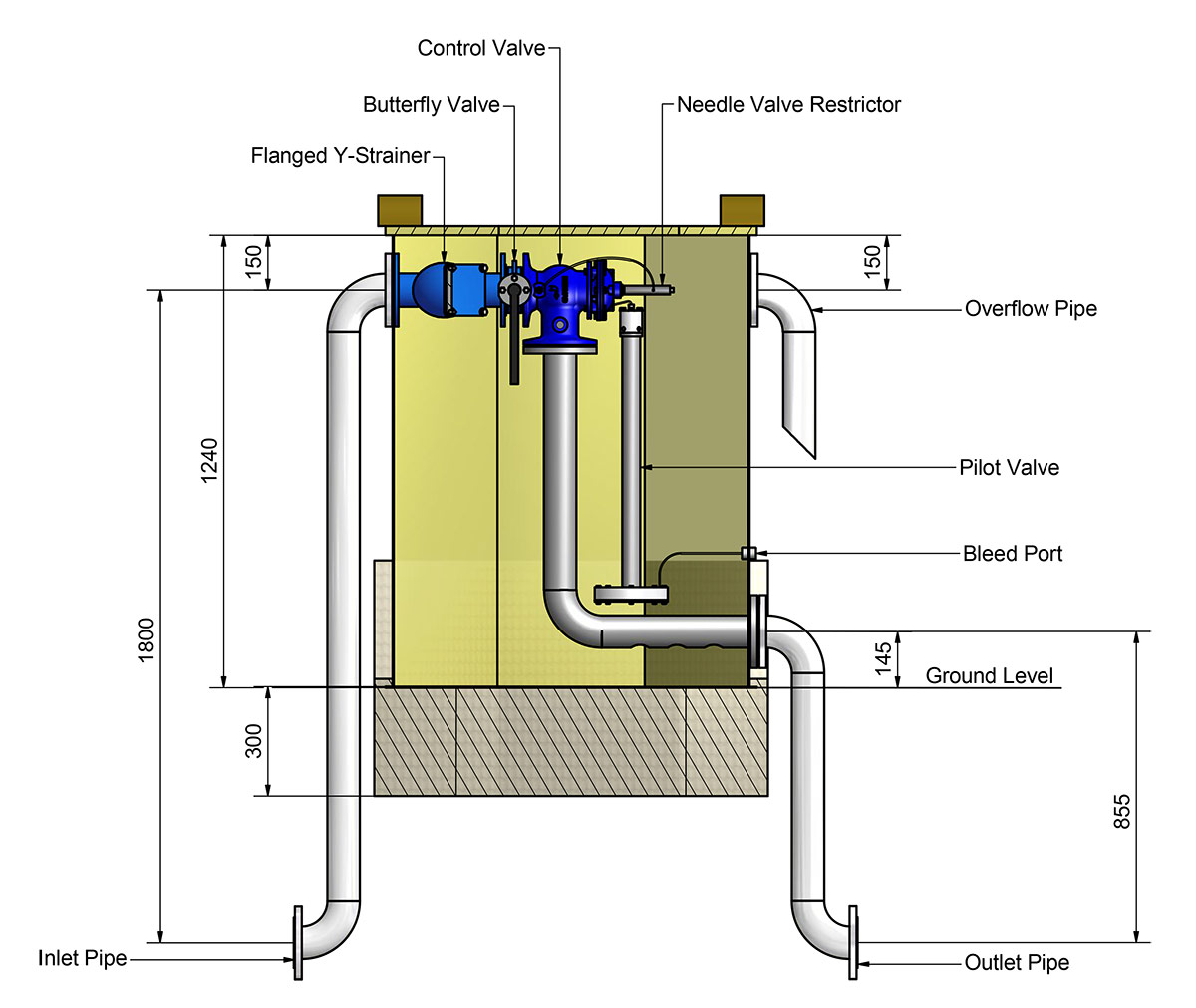
80 AND 100MM BREAK PRESSURE TANKS
CONSTRUCTION
The break pressure tank consists of the following:
- 1000L 3cr12 stainless steel tank
- basket strainer with flush valve
- butterfly valve for isolation
- hydraulic control valve
- self-cleaning needle restrictor
- diaphragm operated level control pilot
OPERATION
The diaphragm pilot valve opens and closes the control valve as system demand fluctuates. The flow into the tank is automatically regulated to match the system demand thereby ensuring that the velocity in the upstream pipeline is limited to the design flow rate. Opening and closing occurs gradually to prevent unwanted surges and water hammer.
Installation
TECHNICAL SPECIFICATIONS
| SIZE | MODEL | MAXIMUM OPERATING PRESSURE | PEAK FLOW RATE |
|---|---|---|---|
| 25 mm | 01LW10 | 90 m | 1 l/s |
| 25 mm | 01LW16 | 160 m | 1 l/s |
| 50 mm | 02LW10 | 90 m | 2.6 l/s |
| 50 mm | 02LW16 | 160 m | 2.6 l/s |
| 80 mm | 03LW10 | 90 m | 7 l/s |
| 80 mm | 03LW16 | 160 m | 7 l/s |
| 100 mm | 04LW10 | 90 m | 16 l/s |
| 100 mm | 04LW16 | 160 m | 16 l/s |
High pressure ratings available on request
25 and 50 mm Break Pressure Tank
Operation and Maintenance
Installation
The Break pressure tank should be installed firmly in a concrete base. It is important that the tank is level to ensure correct operation
Start up – Troubleshooting
| SYMPTOM | PROBLEM | ACTION |
|---|---|---|
| 1. Break pressure Tank Valve doesn’t open | a. Check that there is sufficient upstream Pressure by screwing a pressure gauge into the strainers flush valve | a. Restore system pressure |
| 2. Break pressure tank seems incapable of supplying demand. | a. Strainer blocked b. Check system demand there may be a broken pipe |
a. Flush strainer using ball valve b. Repair leak |
| 3. Break pressure tank overflows. | a. System is back feeding from another supply b. Upstream pressure exceeds 90m c.Bleed Port on the side of tank is blocked d. Tank valve diaphragm is faulty |
a. Isolate the two zones b. Consult manufacturer c. Unblock the Bleed Port to allow condensation to drain from the Tank Valve d. Replace the diaphragm. |
| 4. Valve closes but leaks slightly | a. Valve seal or seat is faulty | a. Remove Seat Retainer bolts and inspect the seal and seat replace if necessary. Alternatively replace the Tank Valve with a service exchange unit. |
To protect the systems both upstream and downstream of the Break pressure tank, it is important to only partially open the butterfly valve while filling the pipeline. Once the line is filled the butterfly valve should be opened fully. At this stage it is recommended that the ball valve on top of the strainer be opened for a few seconds to flush out any debris, which may have reached the strainer.
80 and 100 mm Break Pressure Tank
Operation and Maintenance
Installation
The Break pressure tank should be installed firmly in a concrete base. It is important that the tank is level to ensure correct operation.
Start up – Troubleshooting
| SYMPTOM | PROBLEM | ACTION |
|---|---|---|
| 1. Break pressure Tank Valve doesn’t open | a. Check that there is sufficient upstream Pressure by screwing a pressure gauge into the strainers flush valve | a. Restore system pressure |
| 2. Break pressure tank seems incapable of supplying demand. | a. Strainer blocked b. Check system demand there may be a broken pipe |
a. Flush strainer using ball valve b. Repair leak |
| 3. Break pressure tank overflows. | a. System is back feeding from another supply b. Upstream pressure exceeds 90m c. Bleed Port on the side of tank is blocked. d. Needle restrictor has blocked. |
a. Isolate the two zones b. Consult the manufacturer c. Unblock the Bleed Port to allow condensation to drain from the pilot Valve d. Close the butterfly valve, unscrew the needle restrictor and clean out any debris. |
| 4. Valve closes but leaks slightly | a. Valve seal or diaphragm is faulty | a. Close the butterfly valve, remove the control valve actuator and replace faulty components. |
To protect the systems both upstream and downstream of the Break pressure tank, it is important to only partially open the butterfly valve while filling the pipeline. Once the line is filled the butterfly valve should be opened fully. At this stage, it is recommended that the ball valve on top of the strainer be opened for a few seconds to flush out any debris, which may have reached the strainer.