Break pressure tanks provide a highly reliable solution for reducing pressure in small-scale bulk and reticulation water supply networks. Commonly used in rural areas where maintenance access is limited, they offer several advantages over conventional pressure-reducing valve installations.
• Require minimal maintenance
• Do not “hunt” or compete with each other within the same system, unlike pressure-reducing valves
• Offer a higher turn-down ratio than conventional pressure reducing valves
• In the event of failure, the downstream pipeline remains protected from excessive pressure
• Feature fewer components than conventional pressure reducing installations
• Constructed from 3CR12 stainless steel, making them suitable for potable water systems Note: If raw water is used during system testing, surface corrosion may occur. It is recommended that only potable water be used in these tanks.
• 304 stainless steel tanks are available for higher corrosion resistance, though they carry an
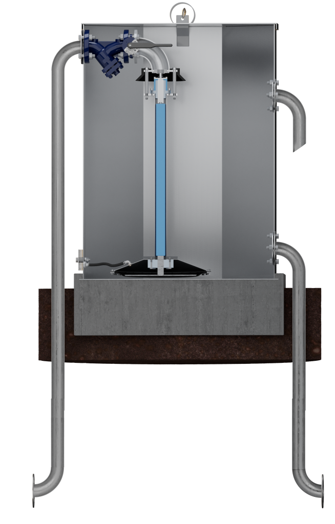
The break pressure tank operates using simple mechanical principles. Incoming water pressure opens the valve by exerting force on the sealing assembly. As the water level inside the tank rises, pressure increases on the diaphragm located at the base of the control valve. The diaphragm’s larger surface area ensures that once the tank reaches full capacity, the resulting force created by the static water pressure in the tank acting on the diaphragm is sufficient to close the valve. This system balances two opposing forces, pressure from incoming water and the diaphragm’s response, allowing the valve to open and close gradually in response to fluctuating system demand. This ensures that the velocity in the upstream pipeline remains within design limits, preventing water hammer and pressure surges.
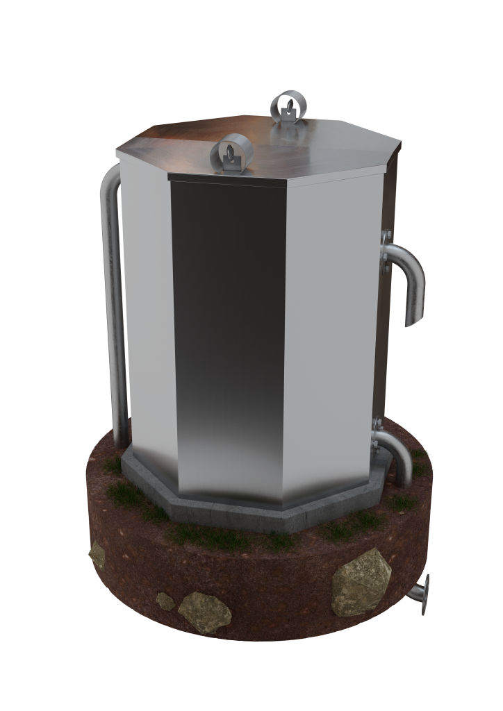
A complete break pressure tank system
includes:
• 1000L 3CR12 Stainless Steel tank (304 optional)
• Basket strainer
• Butterfly valve for isolation
• Diaphragm-operated level control valve
• Inlet, outlet, and overflow pipework
• Lockable lid
The break pressure tank must be securely installed by casting it into a concrete base. During installation, ensure the lid is in place to prevent distortion of the tank. It is essential that the tank is level to ensure proper operation and system performance.